• About
    • Resume
A Game Developer also plays some guitar

Category Archives: Computer Graphics

3ds-max-exporter-plugin

June 15, 2011 9:50 pm / 1 Comment / Benny Chen

把两年前的那个3ds max导出插件项目上传到了google code,代码基本上已经能嗅到铁锈的味道了。现在再上传,一来作备份,二来open source是一件光荣的事情,或许会有人需要它。

地址:

http://code.google.com/p/3ds-max-exporter-plugin/

介绍:

This project was developed with 3DS Max 9 SDK in C++, Visual Studio 2005. This exporter plug-in is aimed to export 3D mesh data from 3DS Max into a predefined file format. These mesh data includes vertices, texture, normals, skeletal animation, etc.

The project was kinda old and becoming a legacy. I developed it in 2009, but never have any update since that. Recently, I am more and more realizing the importance of being open source. So this is why after such a long time I decided to upload it onto Google Code.

I uploaded all the related docs and source code here, for anyone in need. And I would feel extremely flattered if anyone thinks it helpful.

Articles from my blogs about this plugin:
1st part: My Footsteps of Programming 3DS Max Exporter Plug-in (1)
http://www.bennychen.cn/2009/11/my-footsteps-of-programming-3ds-max-exporter-plug-in/
2nd part: My Footsteps of Programming 3DS Max Exporter Plug-in (2)
http://www.bennychen.cn/2010/05/my-footsteps-of-programming-3ds-max-exporter-plug-in-continued/

Introduction to Source Directory:

– CSMExporter is the 3dmax exporter project;
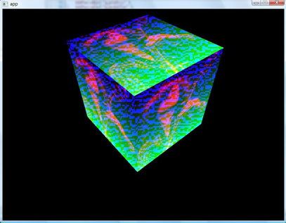
– RenderCSM is a MFC project used to render a CSM file exported from CSMExporter;
– CrowdSimulationModelExporter.dle is the generated 3ds max plugin file outputted from CSMExporter project;
– Doxygen_Docs is the html documentation generated by Doxygen for both projects ‘CSMExporter’ and ‘RenderCSM’;

Posted in: 3D, Computer Graphics, Game Programming, My Projects / Tagged: 3dsmax, exporter, plugin

DX 2010 June不再支持VS 2005

October 24, 2010 11:25 pm / Leave a Comment / Benny Chen

用cmake生成OGRE的项目文件,却出不来Sample项目。cmake的输出信息中提示Skipping samples build,因为Dependecies中的OIS没有编译成功,有以下错误:

dxguid.lib(dxguid.obj) : fatal error LNK1103: debugging information corrupt; recompile module

google了一下,发现很多都是说因为某个版本的DX不再支持VC6了,但我用的是VS 2005,不过DX SDK版本是最新刚刚下载的,猜想出现这个错误是不是也是因为DX和VS版本兼容的问题。

果然,我的DX版本是June 2010,官方网站上申明这个版本开始支持VS 2010,但不再支持VS 2005了。

The June 2010 DirectX SDK includes support for Visual Studio 2010. The DirectX SDK will continue to support Visual Studio 2008 as well. However, Visual Studio 2005 will no longer be supported.

解决办法:

    • 我一直是使用VS2005,好吧,我承认它或许有些过时了,换VS 2008/2010
    • 用一个较早版本的DirectX SDK,February 2010 release是最后一个支持VS 2005的版本
    • 一个将就的解决方案,将对Dependencies的编译从debug换成release
      Posted in: Computer Graphics / Tagged: dx, ogre, sample, support, vs 2005

      My Footsteps of Programming 3DS Max Exporter Plug-in (continued)

      May 12, 2010 4:21 pm / 2 Comments / Benny Chen

      Oh my goodness, how long has it been since I wrote the first part of this article? What on hell was I buzzing around for during this period which seemed years to me? This plug-in is nearly becoming a legacy for me. Now it’s time to bring it back and finish the remaining parts. And I will also upload the whole project’s source code and related docs later.

      First part of this article: http://www.bennychen.cn/?p=640

      Predefine mesh file format

      After we’ve got some basic concepts about 3DS Max, now it’s time to define our own mesh file format. It’s very hard to directly define a format from the scratch. Researching some already typical and mature file formats is a good starting point. Recommended by my tutor, I chose .md2 & .md3 formats as my learning material which are famous for being used in the Quake series game. Based on several days’ research on them, I defined my own mesh file format, which is sort of like .md2 & .md3 but also differs from them at some point.

      I did not just define one format. They are a suite of formats, see the following table.

      File Type
      File Format
      Basic mesh file
      *.CSM (Crowd Simulation Model)
      Texture
      *.jpg, *.bmp, ……
      Animation
      *.AM
      Animation Configuration
      *.CFG
      Mounting Configuration
      *.CSM_PACK

      There are 5 parts in total. But some of them are not necessary. Only one file is essential – the basic mesh file, which is named as CSM( Crowd Simulation Model ), because at that time I programmed this plug-in mainly for a crowd simulation project. The texture part is the textures file used by the mesh. If a mesh includes animation, the AM file( short for animation ) and animation configuration file(.CFG) are also needed. My format also supports mesh mounting, so if a mesh is mounted by several sub-meshes, .CSM_PACK is used to store the mount info.

      These are some of the features of my format.

      • Support multi-texture
      • Support skinned animation
      • Decouple mesh and animation
      • Support animation configuration
      • Support mesh mounting

      And the 2 figures below are the inside structure of CSM and AM. If you want to know more detail of them, later I will upload the docs.

      I stored my animation data in .AM file, bone by bone, animation by animation, and frame by frame.

      Export static mesh data

      OK, so far, all the preparation work is done. We can finally start the programming process.

      For the last 2 steps, I will not present very detailed info here. I will only talk on the difficulties needed to overcome when I programmed them. All the programming job is strictly based on the format we defined last step. For more detail, please turn to my source code.

      Firstly we need to handle the static mesh data. In this step, some difficulties are.

      1. Transformation between different types of coordinate system.
      Basically 3DS Max uses right-hand coordinate system. But some common rendering system( i.e. DirectX ) uses left-hand coordinate system. They have totally different coordinate systems, see figure below. So, the coordinate data needs to be transformed before outputting. See the figure below, the left is a typical rendering system’s coordinate system, and the right is of 3DS Max.

      About how to transform, you can refer to this paper – 《一种不同坐标系之间的变换矩阵的转换方法》by 杨卫东&刘玉树.

      2. Handle mesh with multiple textures.
      This is a tricky problem. We know that a single vertex could be shared by different faces, so if these faces are attached with different textures, the vertex should have multiple UV coordinates. This leads to the fact that we need to split the vertex into multiple vertices, so that we can ensure one vertex only maps to one UV coordinate. And the whole mesh needs to be reorganized.

      From my CSM format definition, you may have found that a mesh is comprised of multiple submeshes. Actually the submeshes are split based on textures, that is, vertices using the same texture are categorized into one submesh. So if an original vertex is using 2 textures, this vertex is firstly split into 2 vertices and will exist under 2 submeshes respectively.

      3. Vertex normal
      This is another painful issue. About this topic, I once wrote an article in my blog before. Turn to it here.

      Export skinned animation

      Now, we have come to the most complex, most sticky part of the whole work. I can still remember the time, the pain and the effort when I tried to tackle this problem. Those memories are so unforgettable. But they all deserve.

      Why I did it so painfully was that, firstly I was still not familiar with the mechanism of bone animation at that time, secondly the mechanism of 3DS Max skeletal system is hard to figure out, whether its bone system or biped system, lastly, decouple the vertex data and the animation data is another challenge.

      About the computational process of bone animation, thanks to this blog, it is the key article that helped me accomplish the whole work.
      http://www.cnblogs.com/neoragex2002/archive/2007/09/13/Bone_Animation.html

      Screenshots

      The figure below is my exporter plug-in UI. The upper part is used to include animations, which will later generate .CFG file. Ant the lower part is used to configure mesh mounting, which will later generate .CSM_PACK file.

      And here is an example of exporting. On the back is the 3ds max software interface, rendering a mesh with or without some animation. And on the front is the mesh viewer developed by me, which renders the same mesh with the same animation.

      This is another example, the Tiananmen Gate.

      Posted in: Computer Graphics / Tagged: 3ds max, exporter, plug-in, 导出插件

      My Footsteps of Programming 3DS Max Exporter Plug-in

      November 20, 2009 9:03 pm / 4 Comments / Benny Chen

      Several months ago, I achieved to develop a 3DS Max exporter plug-in. But until recently, I didn’t get the time to jot down something about my experience while developing it. Finally, thank God, I am starting to write this article, in case that several years later I totally forget how I did it at that time.

      As you know, 3DS Max is a powerful tool for creating 3D models, especially widely-used in games. But generally we cannot directly get our model from 3DS Max, otherwise, we need a sort of middleware to retrieve specified model data we need from 3DS Max and export them into a specific type of file. This middleware is right the exporter plug-in.

      OK, with this concept in mind, let’s get started.

      Step by step, I will roughly present my footsteps of programming a 3ds max exporter plug-in based on 3DS Max 9 SDK.

      Get familiar with 3DS Max and SDK

      As we all know, there are a series of 3DS Max versions. Firstly you need to choose one to program based on. At the time of my embarking on this plug-in, the latest version is 3DS Max 2009. However, I chose Max 9 because it is already a widely-used and popular version. Most importantly, my laboratory was using Max 9.

      Before doing some real programming jobs, it is pretty important to gain some basic concepts of 3ds max. We needn’t to be a perfect 3D designer ourselves, but these are the essential concepts we must know.

      • what is a Node in 3ds max
      • the hierarchical chart of nodes
      • how materials are attached to a node
      • what is a node’s Modifier
      • key-frame animation and how bone nodes are attached to normal nodes
      • the Biped technique

      The fact is, the more we want to export from 3DS Max, the more we need to concern about it. For example, if we also want to export the data of camera or light from Max(meshes for games usually don’t export these data), we must apprehend what is a camera or light node in Max and how they work with other nodes.

      But how the hell could we get the detail of these knowledge? Turn to the Max SDK Document, whenever you have any confusion with Max. Besides, we can also log on to Autodesk’s official Web site for more help.

      BTW, the assumption here is that you are already familiar with some 3D concepts, like vertex, triangle, mesh, texture, space transformation, skinned animation, etc. If you are still a 3D newbie, you’d better figure them out firstly.

      To be continued…

      Predefine mesh file format

      Export static mesh data

      Export skinned animation

      Posted in: Computer Graphics / Tagged: 3ds max, exporter, plug-in, 导出插件

      Unproject

      July 30, 2009 11:19 am / 1 Comment / Benny Chen

      Unproject即反投影,将一个坐标从投影空间中反投影到视图空间。对于Project操作,很容易,直接用投影矩阵乘以视图空间的坐标即可,即:

      posProj = posView * matrixProj

      其中设posView = (x, y, z, 1)是视图空间的某一位置点的坐标,posProj = (x’, y’, z’, w’)为投影空间中该点的坐标,matrixProj为投影矩阵。我们知道,因为投影矩阵的特殊性,有w’ = z,即视图空间的深度值存储在投影空间的w值中,这样posPorj的xyz坐标值在除以了w值之后,就有了近大远小的透视效果。注意:只有在除以了w值之后才会有,x’/w’,y’/w’∈[-1,1]且z’/w’∈[0,1],即在那个所谓的半个正方体中了。

      那么对于Unproject操作呢,是不是直接posView = posProj * inverse( matrixProj )就可以了呢,如果知道x’y’z’w’值,当然是正确,但关键问题是,大多数情况下,我们所知道的只是x’/w’,y’/w’以及z’/w’的值。

      DX提供了一个函数D3DXVec3Unproject,可以做反投影,不过它只能在C++代码里使用(shader里没法使用),而且需要注意的是,这个函数是对屏幕空间的坐标进行的反投影(所以这个函数还需要传入一个viewport参数),务必不要将投影空间的坐标作为参数传递给这个函数。

      我需要写一个自己的反投影函数,不妨从上面的这个公式推导:posProj = posView * matrixProj,因为我们现在已知的是x’/w’,y’/w’以及z’/w’的值,不妨设posProj’ = (x’/w’, y’/w’, z’/w’, 1 ),所以这个公式改为:posProj’ * w’ = posView * matrixProj。

      因为一般投影矩阵是像这样一种形式:

      projmatrix

      于是有拆分posProj’ * w’ = posView * matrixProj后,有:

      posProj’.x * w’ = posView.x * xScale;
      posProj’.y * w’ = posView.y * yScale;
      posProj’.z * w’ = posView.z * Q – Q*zn;
      w’ = posView.z

      上面构成一个方程组,解这个方程组,可得:

      posView.z = Q*zn / ( Q – posProj’.z )
      posView.x = posView.z * posProj’.x / xScale
      posView.y = posView.z * posProj’.y / yScale

      至此反投影完毕。

      反投影一般比较常见的是在鼠标拾取(picking)的例子中,而那里投影空间的点取的是近屏幕上的点(posProj’.z = 0),因为这样上面的公式就会得到一个比较简化的特例:

      posView.z = zn
      posView.x = posProj’.x * zn / xScale
      posView.y = posProj’.y * zn / yScale

      Posted in: Computer Graphics / Tagged: D3DXVec3Unproject, unproject, 投影矩阵, 投影空间, 视图空间

      顶点法线

      July 23, 2009 4:27 pm / 2 Comments / Benny Chen

      本来以为前一段时间写的3d max导出插件已经没有什么大的问题了,但有没有问题,完善不完善,真不是凭感觉就OK的,必须有足够广泛的测试用例测试后,才能够证明。

      这不,最近开始研究并写一些光线跟踪的例子了,这当然离不开模型的法线,于是在进行当中我就发现,我的导出插件所导出的法线是不完善的。

      在原来的插件中,我让顶点的法线就直接等于其所在的三角形面的面法线(多个面共享1个顶点,则会导出多个顶点,这些顶点位置相同法线不同),但对于光照模型,面法线只能支持到Lambert,为了支持Gouraud, Phong等其他模型,则必须使用顶点法线(为什么?稍后解释)。

      这里提出了顶点法线和面法线,首先需要清楚的理解并区分这两个概念。

      面法线很容易理解,即垂直于三角形面的一条法线。那顶点法线又从何而来呢,严格的从法线的定义上来说,其实顶点是不存在法线的,那为何又有顶点法线这个概念的。让顶点也拥有法线,是为了在光照计算时,能够在多面体的表面获得一种平滑的效果。

      更具体的说,如果不使用顶点法线(就像我的3dmax导出插件原来就直接让顶点法线等于其面法线一样),一个三角形面的三个顶点的光照计算按照其所在面的面法线来计算,因为三个顶点的法线相同,则与光照方向求点积之后的结果也相同,这样三个顶点将会获得相同的光照效果,之后,光栅化再怎么插值,整个表面也都只是一种光秃秃的效果。(如图1)

      而如果使用顶点法线,同一个面的三个顶点的法线就不一定相同了,这样通过光栅化后,就能在多面体的表面获得一种平滑过渡的光照效果。(如图2)

      于是,弄清楚了这个后,我需要再次修改我的3dmax导出插件了,需要计算并生成新的顶点法线。那顶点法线该如何计算呢,对于这个我在这里就不详述,Max Wagner的《Generating Vertex Normals》这篇文章说的很详细清楚,从最简单的到逐步优化的生成算法一一都有介绍,可以去google找一下。

      而3dmax的SDK开发文档里对顶点法线的计算也有介绍,3dmax提供了一个smoothing group的概念,这对于像立方体盒子这种表面并不是平滑过渡的模型,计算它们的法线将会带来很大的帮助。Wagner的文章里也说了,对于像立方体这样的模型,顶点法线不能简单的等于(共享该顶点的面的)面法线的平均值,因为这些面之间的过渡并不平滑。按照3dmax的概念,这些面不属于同一个smoothing group。何为smoothing group,这是3dmax根据表面之间的平滑过度情况,进行的分组。比如立方体,因为6个面之间两两都是相互不平滑的,所以一共会有6个smoothing group。每个面所属的平滑组的ID,程序员是可以直接读出的。

      下面这两张图,是我在修改前和修改后的光照效果,对比很明显。

      lambert 图1:基于面法线的光照

      gouraud图2:基于顶点法线的光照

      Posted in: Computer Graphics / Tagged: 面法线, 顶点法线

      诡异的画面

      July 16, 2009 5:55 pm / Leave a Comment / Benny Chen

      对shader文件做了一些修改,但还只是简单的渲染一个带纹理的盒子。出来的结果居然是这样的诡异,荧光闪闪,还带着雪花满盒子飘……

      雪花bug

      shader的错误的确很难查找,尤其是在编译通过只剩下逻辑错误的时候。最后错误的原因却又是如此的简单,我把PS的返回值写成了float,而应该是float4,我不小心漏掉了4,于是造成了这样诡异却绚烂的艺术效果,留文以作纪念。

      Posted in: Computer Graphics / Tagged: pixel shader

      Some Tests

      July 8, 2009 9:30 pm / Leave a Comment / Benny Chen

      在最近的项目中,尝试进行了一些小实验,并记录了数据作为比较。实验机器的显卡是NVidia Geforce 8800 GT。

      1. Skinning

      skinning on CPU

                                skinning on CPU

      skinning on GPU

                                skinning on GPU

      从图中可以清晰的看出,对于骨骼蒙皮计算,CPU和GPU的差距可见一斑,GPU比CPU要快上10倍之多!这就是GPU并行计算的魅力!

      2. Instancing & Stream Output

      人物模型延用上面的这个模型(该模型差不多有1300个面),采用instancing技术渲染上千人(所有的Instance的动画在每一帧保持一致),并且实现了SO的版本,对它们的FPS进行比较。

      Instancing without SO


           1,000 Instances              2,000 Instances             3,000 Instances

      Instancing with SO


           1,000 Instances              2,000 Instances             3,000 Instances

      因为所有的Instance的动画在每一帧都是一致的,所以如果不使用SO技术,则不得不对每个instance都需要进行一次蒙皮动画,这显然是一种浪费。Stream Output技术使得所有的Instance的蒙皮动画只需要执行一次,所以在效率上得到了一定的提高,如下表。

      Number of Instances

      FPS(Without SO)

      FPS(With SO)

      1,000

      40

      56

      2,000

      19

      36

      3,000

      13

      24

       3. Frustum Culling

      换了一个低质量的模型(只有不到200个面),基本上万人级别是没有问题了,加上了Frustum Culling,则可以跑得更快!

      使用3种方法实现了Frustum Culling,前两个都是基于CPU的,最后一个是基于GPU

      1. 顺序执行(最简单的对所有Instance遍历执行Frustum Culling算法)
      2. 四叉树(四叉树裁剪,我这里用四叉树用得有点牵强,因为人物不能移动且必须保持边长为2的N次方的阵型。这么简单的处理四叉树,只是为了做实验比较而已)
      3. GPU上的Frustum Culling(算法基本上跟1是一致的,只不过是在GPU上执行)

      三个方法在同一个视角,使得它们截取和渲染的数量是一致的。总共65536个Instance,当前绘制都是15485个。


                 顺序执行                              四叉树                             在GPU

      效率比较如下表。

      Current Rendering / Number of Instances
      FPS
      (Sequential Frustum Culling)
      FPS
      (Frustum Culling With Quad-tree)
      FPS
      (Frustum Culling on the GPU)
      4388/16384 61 143 102
      15485/65536 16 43 32

      发现最快的是使用四叉树,而GPU的算法反而相对比较慢。原因很有可能是后者需要处理GPU和CPU的同步问题,在GPU进行Frustum Culling需要CPU从GPU读取Frustum Culling执行的结果(为了知道有多少个instance需要被渲染),在DX10的SDK文档里可清楚的写着,从GPU向CPU进行Map读取操作,是比较严重影响效率的,因为总有一方要停下来去等待另外一方的数据。

      Posted in: Computer Graphics / Tagged: frustum culling, instancing, skinning

      Get streaming output statistics

      July 8, 2009 1:33 pm / Leave a Comment / Benny Chen

      有时候需要知道stream output了多少个数据,这需要借助于DX10中的ID3D10Query,步骤如下:

      1. 创建D3D10_QUERY_DESC结构,设置D3D10_QUERY_DESC::Query为D3D10_QUERY_SO_STATISTICS,表明要调查的是SO的数据,设置D3D10_QUERY_DESC::MiscFlags为0;
      2. 通过ID3D10Device::CreateQuery()创建ID3D10Query;
      3. 用ID3D10Query::Begin()和ID3D10Query::End()函数包裹需要调查的SO代码;
      4. 通过ID3D10Query::GetData()获取SO的统计数据,填充在一个D3D10_QUERY_DATA_SO_STATISTICS

      示例代码如下:

      // 创建ID3D10Query
      ID3D10Query *d3dQuery;
      D3D10_QUERY_DESC d3dQueryDesc;
      d3dQueryDesc.Query = D3D10_QUERY_SO_STATISTICS;
      d3dQueryDesc.MiscFlags = 0;
      m_pD3DDevice->CreateQuery( &d3dQueryDesc, &d3dQuery );
      
      // ...... ......
      
      // 统计SO信息
      d3dQuery->Begin();
      // ......draw something with SO......
      d3dQuery->End();
      
      // ......最好在这里放置一些代码,填置CPU的空闲......
      
      // 获取SO信息
      D3D10_QUERY_DATA_SO_STATISTICS soData;
      while ( S_OK != d3dQuery->GetData( ( void* )&soData, sizeof( soData ), 0 ) );
      

      值得注意的是,GetData一定要用while包裹,因为ID3D10Query从GPU获取数据是异步的(ID3D10Query继承自ID3D10Asynchronous)。这也是为什么最好能在GetData之前放置一些代码,因为CPU要等待GPU的数据,不如让CPU先去做些其他的事情,不要把CPU浪费在毫无意义的while循环等待上。

      Posted in: Computer Graphics / Tagged: D3D10_QUERY_SO_STATISTICS, ID3D10Query, stream output

      ConstructGSWithSO

      July 1, 2009 5:07 pm / 1 Comment / Benny Chen

      如果要使用SO(Stream Output),则在shader中必须使用ConstructGSWithSO函数来构造SO的GS,ConstructGSWithSO有两个参数。

      • VertexShader/GeometryShader – shader变量,因为SO的数据可以来自GS,也可以来自VS(如果GS为NULL),所以该参数可以是一个VertexShader,也可以是一个GeometryShader。(shader变量一般通过CompileShader函数获得)
      • Semantics – 描述SO的数据的semantic,该semantic须与上一个参数(shader变量)的shader函数的输出相一致。这个参数的格式要求比较变态,所以举例子说明比较好。

      现有一个VS如下,需要SO它的输出数据:

      struct VSInput
      {
          ……(略)
      };
      struct VSOutput
      {
          float3 pos : POSITION;
          float2 tex : TEXCOORD;
      };
      VSOutput VS VSInput
      {
          VSOutput o;
          ……(略)
          return o;
      }
      

      那么ConstructGSWithSO函数应该这么写:

      GeometryShader gsSkinningSO = ConstructGSWithSO( CompileShader( vs_4_0, VSSkinning_SO() ), “POSITION.xyz; TEXCOORD.xy” );

      看粗体部分的第二个参数,首先是双引号的字符串形式的,双引号内逐个列出了VSOutput的semantic,每个semantic同时要用.xyz,.xy这样的形式标明出它的维数(特别注意,如果只是一个float或uint的一维数据,同样也需要用.x来标出它是一维的!)。各个semantic之间用分号隔开,但注意,最后一个semantic后面不需要加分号(不然创建shader失败!)。

      Posted in: Computer Graphics / Tagged: ConstructGSWithSO, DX10

      Post Navigation

      ← Older Posts
       

      LinkedIn

      Milan Petrovic

      Categories

      • In My Life (25)
        • A Day in the Life (8)
        • English Learning (2)
        • Learn a Word (7)
        • Something In The Way (8)
      • Music Heaven (8)
        • Guitar (1)
        • In Concert (1)
        • Lyrics (3)
      • OK Computer (54)
        • 3D (3)
        • C++ (10)
        • Computer Graphics (15)
        • Game Programming (23)
        • iOS (6)
        • Linux (1)
        • Lua (9)
        • My Projects (3)
        • Some Experiences (9)
        • Talking in Code (2)
        • Unity (2)
      • Quotations (2)
      • Uncategorized (1)
      • Visca Barça (24)
        • FCB BJ (5)

      Recent Posts

      • [译]优化你的手机游戏(没有延迟的,才是健康的)- 一篇给游戏美术设计师读的文章
      • 新浪微博API for MOAI
      • 稍后继续
      • Unity Developer ++
      • Another Thread @ Moai Forum
      • 1st Day of Golden Week
      • 为SyntaxHighlighter添加新语言
      • 基于Lua的State Pattern
      • Class Diagram of Pacman
      • 基于Moai的Pacman

      Recent Comments

      • 约修亚_RK on 为SyntaxHighlighter添加新语言
      • 爱装的小男孩 on 小心DLL链接静态库时的内存错误
      • happyfire on Game Loop的几种实现方式
      • William on 新浪微博API for MOAI
      • Benny Chen on 新浪微博API for MOAI
      • your man on 新浪微博API for MOAI
      • 你家男人 on 稍后继续
      • 逍遥 on 关于对std::vector的遍历
      • papa on Unity Developer ++
      • T客网 ︱ Techpot » Blog Archive » iOS开发与OpenGL ES相关问题整理(1) on iOS开发与OpenGL ES相关问题整理(1)

      Tags

      2d 3D 3dsmax 3ds max air Apply architecture Asia tour barca Beijing bilbao binary search blocked bob boost bruce springsteen C++ capo CGContextDrawImage Champions League Change DLL DX10 eval exporter flash framework frustum culling game game engine iniesta ios linux lua Moai opengles pacman plug-in plugin 北京 导出插件 崩溃 巴萨 游戏引擎 踢球
      © Copyright 2026 - A Game Developer
      Infinity Theme by DesignCoral / WordPress